 Rotate View
- General Settings
- Step-By-Step
- Tips and Tricks
- Related Tools
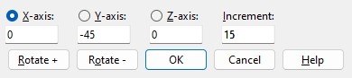
X-axis, Y-axis, and Z-axis : The global axis you are wanting to rotate about. This also displays the number of degrees of rotation around the particular axes. Validation allows an entry between +/-.001 and +/-180.
Increment : Any number of degrees between .001 and 180. User and Site Options > Modeling > " Rotation increment " sets the default for this field.
Rotate + : Rotates the view counterclockwise around the selected axis. The view will be rotated the number of degrees that are entered to the " Increment " field.
Alternative : Select the left arrow key on your keyboard.
Note : The degree values in the X-axis, Y-axis and Z-axis will change as the rotate happens.
Rotate - : Rotates the view clockwise around the selected axis. The view will be rotated the number of degrees that are entered to the " Increment " field.
Alternative : Select the right arrow key on your keyboard.
Note : The degree values in the X-axis, Y-axis and Z-axis will change as the rotate happens.
OK : Closes the Rotate View window and leaves the view rotated as is.
1 . Click the Rotate View icon, which is pictured above. The icon can be found on the Layout page > Navigate section.
Alternative: Invoke Rotate View using the Find Tool by searching the command name and clicking the icon, which is pictured above.
Learn more about alternative methods for launching commands.
2 .The status line prompts, "Locate a reference point:". Various Locate options become active with Locate - Pan - Return mouse bindings. Your view will rotate around this reference point. Left-click ( Locate ) where you want the reference point to be located.
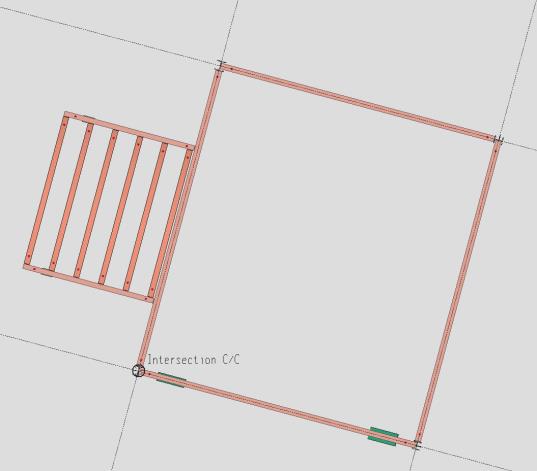
Alternative: Press Esc or right-click (Return) to cancel the command.
3 . The status line prompts, "Locate optional direction point:". Various Locate options become active with Locate - Pan - Return mouse bindings. Left-click ( Locate ) where you want the directional point to be located.
Note : Locating a directional point will immediately rotate the view by aligning the horizontal axis with the imaginary line formed between the reference point and the directional point.
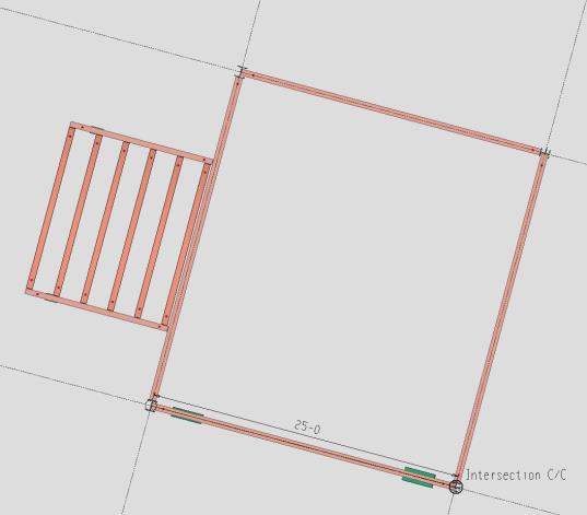
Alternative: Press Esc or right-click (Return) to skip adding the optional direction point and continue to the next step.
4 . The Rotate View window opens and you can rotate the view along the first point selected in step 2. When you are done rotating the view, press the " OK " button to close the Rotate View window.
Note : When the rotate window opens, you may notice values displayed below the X-axis, Y-axis, or Z-axis. These values correspond to the rotation set by the reference point and directional point relative to the global axis.
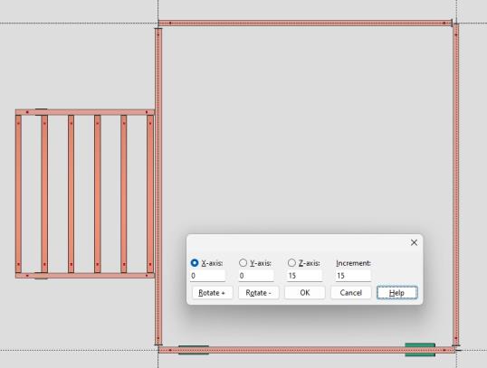
Alternative: Pressing Esc or cancel undoes the rotation(s) and ends the command.
5 . At this point you have not saved any changes to your current view; you have simply rotated it.
If you are in an erection view : Use Save View As to actually create a new view or replace your current view. Or use Undo View Change or Revert to undo the changes to your current view.
If you are in member isolation : Press the Save button to overwrite your current member view or to save the edited member view as a new member view.
- Modeling (where Rotate View is a tool)
- Current view location (changed by Rotate View )
- Save View As (to save changes made by Rotate View )
- Undo View Change (undoes Rotate View )
- Snap to Adjacent Surface (alternative to Rotate View )
- Snap to Farside Surface (alternative to Rotate View )

